Choosing the right Pockels cell

A practical guide to crystals, applications and drivers. Crystal material and wavelength set the voltage a cell needs; geometry brings it back down; the driver decides how fast it can be switched. Getting a Pockels cell right means choosing all three together - not picking each one on its own.

A Pockels cell is a voltage-controlled optical switch. It uses the Pockels effect - the linear electro-optic effect, in which an applied electric field changes a crystal's polarization-dependent refractive index in proportion to the field. Between crossed polarizers it becomes a Pockels cell shutter, switching in nanoseconds with no moving parts; at intermediate voltages, a Pockels cell modulator.

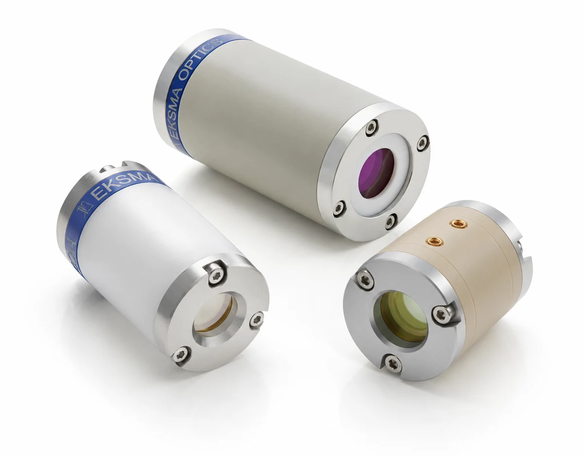
Three EKSMA Optics Pockels cells side by side, showing their clear apertures and high-voltage connectors

Inside the Pockels cell

Modern lasers no longer just produce light - they have to control it at nanosecond speed. Across manufacturing, medicine, research, telecoms and defence, laser systems rely on ultrafast optical switches to shape pulses, isolate amplifiers and extract energy at exactly the right moment. At the centre of that capability sits a deceptively simple component.

First described by Friedrich Pockels in 1893, the linear electro-optic effect that bears his name lets an applied voltage change a crystal's polarization-dependent refractive index almost instantaneously - fast enough to switch a laser beam's polarization state in nanoseconds. That has made the Pockels cell the standard fast, reliable switching element for Q-switching, cavity dumping, pulse picking and regenerative amplification.[1]

A Pockels cell has no moving parts, and it does not open or block a path itself. An electric field changes how a crystal affects the polarization of light passing through it, and a pair of polarizers converts that change into transmission or extinction.

Two states of the same optical train

Figure 1

Voltage off

Extinguished
Pockels cell HV = 0 unpolarized Laser Polarizer (input, 0°) Analyzer (crossed, 90°) HV driver idle beam dump Pockels cell HV = 0 unpolarized Laser Polarizer (input, 0°) Analyzer (crossed, 90°) HV driver idle beam dump

Polarization stays vertical through the unpowered crystal, so the crossed analyzer extinguishes it.

Half-wave voltage on

Full transmission
Pockels cell HV = Vλ/2 unpolarized Laser Polarizer (input, 0°) Analyzer (crossed, 90°) HV driver - pulse applied detector Pockels cell HV = Vλ/2 unpolarized Laser Polarizer (input, 0°) Analyzer (crossed, 90°) HV driver - pulse applied detector

The pulse rotates the polarization 90°, aligning it with the analyzer's axis for full transmission.

Figure 1: basic working principle of a Pockels cell.
Beam path Extinguished path Induced birefringence axis (voltage applied)

The half-wave voltage is set by the crystal material, its length and the beam's wavelength. Alignment is what makes the switch work: if the rotated polarization does not land on the analyzer's axis, extinction ratio - and with it laser power output - drops drastically.[2]

Sometimes the half-wave voltage needed for a single pass is simply too high - high enough to risk damaging the crystal, or beyond what the driver's electronics can deliver. A double-pass configuration is the way around it. A mirror behind the crystal sends the beam back through it, so the light picks up retardation twice per round trip. Driving the cell at only the quarter-wave voltage is then enough: the two quarter-wave contributions add up to a full half-wave, giving the same 90° rotation for half the drive voltage.[2]

One mirror, half the voltage

Figure 2
LASER Polarizer (45°) Pockels cell EO crystal HV = Vλ/4 pass 1: +λ/4 Mirror (the one addition) pass 2: +λ/4 beam re-enters the same crystal on the way back reflected out (polarization now rotated 90°)
Figure 2 - quarter-wave operation. Between fully blocked and fully transmitted the cell can also sit at intermediate voltages for partial transmission, but most laser applications use it purely as a fast two-state switch.

Choosing the crystal material

Not every Pockels cell crystal behaves the same way, and the choice of material lands directly on switching speed, voltage requirement and long-term reliability. Three materials dominate real-world use: DKDP (also called KD*P), BBO, and RTP with its close relative KTP.

Table 1 - DKDP, BBO and RTP/KTP Pockels cells compared.

Property DKDP KD*P BBO beta barium borate RTP / KTP
Field configurationLongitudinalTransverseTransverse
Half-wave voltage< 6.8 kV a< 4.6 kV b< 1.8 kV b
Duty cycle< 5%< 50%< 5%
Repetition ratekHzMHzMHz
Max HV pulse durationmssµs
Piezoelectric resonancesHighLowModerate
HygroscopicYesYesNo
Wavelength range400–1100 nm200–2000 nm400–2700 nm
Clear aperture< 350 mm< 12 mm< 15 mm

a At 1064 nm, independent of aperture. b At 1064 nm and 3.5 mm clear aperture diameter.

Longitudinal field

DKDP (KD*P)

The traditional workhorse for Q-switching. Because the operating voltage is essentially independent of aperture, DKDP cells scale to very large clear apertures. The trade-offs: it is strongly hygroscopic, so it needs a hermetically sealed housing, and it shows the most pronounced piezoelectric ringing of the three - which holds it to lower repetition rates. Still the solid, low-cost choice for single-shot and low-rep-rate Q-switching.[3][4]

Example
PC12SR-1/1-1064
Vλ/2 at 1064 nm
< 6.8 kV
Design
Single crystal

DKDP Pockels Cells

Transverse field

BBO

Electrodes sit along the sides rather than on the optical faces, so the operating voltage scales with the ratio of electrode spacing to crystal length. BBO has the lowest piezoelectric ringing of the three, which suits repetition rates up into the megahertz regime, and it handles high duty cycles and long HV pulses well. Its trade-offs are a smaller aperture than DKDP and a higher drive voltage than RTP, which is why BBO cells are often run in quarter-wave operation.[5]

Example
PCB4D-C-1064
Vλ/2 at 1064 nm
< 4.6 kV (⌀ 3.5 mm)
Design
Double crystal

BBO Pockels Cells

Transverse field

RTP / KTP

Close relatives, set apart by one standout property: a very low half-wave voltage. Lower drive voltage means smaller, faster and less expensive driver electronics. They also support megahertz repetition rates with short HV pulses, are non-hygroscopic so no sealed housing is needed, and reach furthest into the infrared. Ringing sits between the other two, depending on the repetition rate and pulse duration used. Main trade-offs: small aperture and low duty cycle.[4][5][6]

Example
PCR4-1064
Vλ/2 at 1064 nm
< 1.8 kV (⌀ 3.5 mm)
Design
Double crystal (standard)

RTP / KTP Pockels Cells

Where the electrodes sit decides how voltage scales

Figure 3

Longitudinal (e.g. DKDP)

E-field (parallel to beam) Crystal electrode electrode beam E-field (parallel to beam) Crystal electrode electrode beam

Electrodes on the two end faces. Field and beam run the same direction, so the voltage needed is set by the crystal length - not its aperture. That is what lets DKDP cells scale to very large clear apertures without the voltage following.

Transverse (e.g. BBO, RTP/KTP)

E-field (perpendicular to beam) Crystal electrode electrode d L beam E-field (perpendicular to beam) Crystal electrode electrode d L beam

Electrodes along the sides. The field runs across the crystal while the beam runs along it, so the voltage scales with the ratio d / L - a longer crystal means a lower voltage, and a bigger aperture means a higher one.

Figure 3 - longitudinal (left) and transverse (right) electrode configurations. This is the reason aperture is free in DKDP and expensive in BBO and RTP/KTP.

Voltage is only half the story. Every high-voltage pulse also makes the crystal physically flex, and the crystal keeps vibrating in response - piezoelectric ringing. That vibration modulates the retardation the cell is supposed to be holding steady, so the optical response stops being a clean rectangle. Figure 4 puts a BBO cell next to two DKDP cells under a single HV pulse.

Optical response to a single high-voltage pulse

Figure 4

BBO 3 × 3 × 25 mm

120 80 40 0 Uₔ / mV 120 80 40 0 U₄ / mV

DKDP ⌀ 12 × 24 mm

120 80 40 0 Uₔ / mV 120 80 40 0 U₄ / mV

DKDP ⌀ 9 × 20 mm

120 80 40 0 Uₔ / mV 120 80 40 0 U₄ / mV
Figure 4 - optical response of BBO and DKDP crystal based Pockels cells affected by a single high voltage pulse. [4][5] Detected signal Ud against time, redrawn from the measurements in those refs. The three pulses start together but are not the same length, so each cell is shown with its own HV pulse window. All three traces stay flat out to 60 µs; the axis is cut at 30 µs so the switching region stays legible.
BBO - low ringing DKDP - high ringing HV pulse applied

The BBO cell holds its level for the whole pulse - a clean rectangle, apart from a ripple far smaller than the step itself. Both DKDP cells never settle: transmission steps up part of the way, overshoots, and falls back before the pulse ends. Nothing about the driver changed - the crystal's own acoustic resonance is modulating the retardation underneath. That is what holds DKDP to repetition rates well under a few kilohertz, while BBO - the lowest piezoelectric ringing of the three materials - runs up into the megahertz regime and takes long high-voltage pulses and high duty cycles in its stride.

Three jobs inside a laser system

The same fast polarization switch does three distinctly different jobs, depending on where it sits and how it is timed. Between them, these three cover very nearly every practical use of a Pockels cell - and each one asks something different of the cell and its driver.

Q-switching

The most common use

The cell sits inside the laser cavity and holds it closed, preventing lasing while the gain medium keeps absorbing pump energy and building a large population inversion. When the cell switches, the cavity opens all at once and the stored energy leaves as a short, high-peak-power pulse rather than a continuous low-power beam.

This is the standard mechanism behind nanosecond-pulsed solid-state lasers - laser marking, range finding, LIDAR.[7]

What it demands
Hold-off voltage and contrast. Repetition rate is governed by pump and gain recovery time, not by the driver - so a high-voltage, low-rate driver is exactly the right profile.

Cavity closed - energy building up

Building up
Gain medium pumped - population inversion builds, cell blocks lasing Gain medium Pockels cell HV = 0 HR mirror (pumped) Polarizer (0°) Analyzer (crossed, 90°) Output coupler (partially reflective) Gain medium pumped - population inversion builds, cell blocks lasing Gain medium Pockels cell HV = 0 (pumped) HR mirror Polarizer (0°) Analyzer (crossed, 90°) Output coupler (partially reflective)

The polarizer, unpowered cell, and crossed analyzer keep the cavity lossy, so the pumped gain medium stores energy instead of lasing.

Cell switched - giant pulse released

Pulse released
Gain medium Pockels cell HV = Vλ/2 HR mirror (pumped) Polarizer (0°) Analyzer (crossed, 90°) Output coupler (partially reflective) Output: giant pulse ns duration, MW-class peak power Gain medium Pockels cell HV = Vλ/2 (pumped) HR mirror Polarizer (0°) Analyzer (crossed, 90°) Output coupler (partially reflective) Output: giant pulse ns duration, MW-class peak power

The half-wave pulse aligns the polarization with the analyzer axis; cavity Q jumps and the stored energy dumps out as a giant pulse in nanoseconds.

Figure 5: Q-switching scheme.
Circulating cavity beam Output pulse / energized HV

Pulse picking

Hardest on switching speed

Here the laser is already producing a continuous train of pulses at tens to hundreds of megahertz - far too fast for many amplifiers or applications to use directly. A cell between crossed polarizers acts as a gate, opening for a few nanoseconds at a time to let exactly one pulse through while blocking the rest, and bringing the repetition rate down to whatever the next stage actually needs.

Because neighbouring pulses can be only nanoseconds apart, this puts more pressure on switching speed and contrast ratio than any other use case.[8]

What it demands
Switching speed above all. At 80 MHz the gate has roughly 12.5 ns of room, so rise and fall time have to fit inside the gap between neighbouring pulses.

One HV gate, timed to a single pulse

Single pulse selected
Input: high repetition-rate pulse train (e.g., 80 MHz) Pockels cell ns-scale HV gate Polarizer (0°) Analyzer (crossed) Picked pulse transmitted All other pulses blocked at the analyzer HV gate timed to one pulse only Input: high repetition-rate pulse train (e.g., 80 MHz) Pockels cell ns-scale HV gate Polarizer (0°) Analyzer (crossed) Picked pulse transmitted All other pulses blocked at the analyzer HV gate timed to one pulse only

Every other pulse arrives while the gate is off, so it stays cross-polarized and is rejected at the analyzer.

Figure 6: Pulse picking scheme.
Untouched pulse (rejected) Picked pulse (transmitted) ns-scale HV gate pulse

Regenerative amplification

Contrast and speed together

The cell becomes the entry and exit gate for a cavity built around an amplifying medium rather than an oscillator. A single seed pulse is switched in, trapped for many round trips while it picks up energy on every pass, then switched back out once it has reached the target energy - turning a weak seed into a high-energy pulse without ever letting the rest of the train interfere.

Unlike Q-switching, which stores energy in the cavity and releases it in one switching event, this starts from an externally supplied seed and needs two switching events per pulse: one to trap it, one to release it. Final energy is set by how many round trips happen in between. It is the central part of many high-energy femtosecond and picosecond systems.[8]

What it demands
Contrast and switching speed together. Two clean switching events per pulse, with enough extinction between them that the rest of the train never leaks into the cavity.

Regenerative amplifier cavity

Cavity layout
Gain medium Pockels cell HR mirror Polarizer (45°) HR mirror Seed pulse in (low energy) Amplified pulse out (high energy) Gain medium Pockels cell HR mirror Polarizer (45°) HR mirror Seed pulse in (low energy) Amplified pulse out (high energy)

The tilted polarizer reflects the incoming seed pulse into the cavity and, once its polarization has switched, reflects the built-up pulse back out along a parallel path.

Figure 7: Regenerative amplifier scheme.
Intracavity beam Seed pulse in Amplified pulse out

Putting it together

In practice, specifying a cell and its driver starts with four pieces of information: beam diameter, operating wavelength, required repetition rate, and required HV pulse duration. They are taken in that order because each one constrains the next.

01

Beam diameter

The clear aperture has to be larger than the beam, both to avoid clipping its edges and to leave room for alignment. For a Gaussian beam we recommend taking the 1/e² diameter, multiplying by 1.5 for the effective total beam diameter, and adding up to 2 mm for alignment.

The crystal is the most expensive part of a Pockels cell, so aperture is the biggest single driver of cost - and in BBO and RTP/KTP it pushes operating voltage up as well, which then limits the achievable switching rate. It is worth reducing beam size before the cell wherever possible.[9]

02

Wavelength

Longer wavelengths need more voltage for a full 90° rotation, and that holds for all three crystal families. Once the voltage is known, there are two crystal-side ways to bring it down. Cell geometry - a longer crystal - is one. A double-crystal design is the other: it splits the required rotation across two crystals driven by the same voltage, so each contributes only part of it. That roughly halves the voltage needed, and has the side benefit of cancelling residual birefringence between the pair.

RTP-based cells use the double-crystal design as standard. DKDP is usually single crystal, though double-crystal versions exist. BBO comes in single, double or even quadruple crystal - as in the PCB4Q-C-1030. The cost is an extra crystal, which is to say a more expensive cell.[8]

03

Repetition rate

This is where the required repetition rate and the voltage just established either fit together or they don't. A driver cannot deliver both high voltage and high repetition rate at once: every switching event charges the cell's capacitance to the target voltage and dissipates that energy through the driver's switching electronics, and both the stored energy and the resulting heat scale sharply with voltage. A driver engineered to reach several kilovolts simply cannot cycle as fast as one built for a few hundred volts.

The HVS-D2-2.5-9.8 reaches 9.8 kV but tops out at 2.5 kHz - exactly the profile a DKDP Q-switch needs, where the voltage is high but the application was never going to run fast. At the other end, the 2DPB3-6000-1.3-Al reaches 6 MHz at only 1.3 kV, the natural partner for a low-voltage BBO or RTP/KTP cell picking pulses down from an 80 MHz mode-locked train.

If the required rate and the voltage set by wavelength and crystal choice don't both fall inside what a single driver can deliver, a better driver is not the fix. Go back and revisit aperture, crystal choice and configuration until the voltage comes down far enough that a workable driver exists.[10]

04

HV pulse duration

Selecting single pulses out of an 80 MHz mode-locked train leaves only about 12.5 ns between neighbours, so the driver's minimum HV pulse duration has to be short enough to isolate one cleanly. A Q-switched cavity demands the reverse: held in its high-loss state for the full pump duration, which calls for a pulse that stretches far longer. Our driver range spans both extremes - minimum durations down to 0 ns in some units, effectively unlimited maximum durations in others via pulse regeneration - but not both extremes in one design. The electronics that produce a clean nanosecond edge and those that hold a stable voltage for microseconds to milliseconds are built to different specifications.

Rise and fall time comes up alongside pulse duration, especially for pulse picking and regenerative amplification, where the edge itself has to fit inside a few nanoseconds. A fast edge has a cost: a bigger crystal or a higher voltage makes it harder for a given driver to deliver, so a demanding rise/fall spec can send you straight back to the aperture and crystal-configuration decisions above.

From requirements to a cell and a driver

Figure 8

Example 1 - Q-switching

Requirements

Beam diameter
6 mm
Wavelength
1064 nm
Repetition rate
100 Hz
HV pulse duration
1 µs

Pockels cell

D-compact/12-1064

Wavelength
1064 nm
Clear aperture
⌀ 11 mm
Transmission
> 98%
Half-wave voltage
< 6.8 kV

Driver

HVS-D2-3-8.6

Max voltage
8.6 kV
Max rep rate
3 kHz
Pulse duration
35–2000 ns
Rise / fall
< 10.5 / < 9.5 ns
Power supply
integrated

Example 2 - Pulse picking

Requirements

Beam diameter
2.5 mm
Wavelength
800 nm
Repetition rate
1 MHz from 80 MHz
HV pulse duration
few ns, 12.5 ns gaps

Pockels cell

PCR6-800

Wavelength
800 nm
Clear aperture
⌀ 5.5 mm
Transmission
> 98%
Half-wave voltage
< 2.1 kV

Driver

2DP-1000-2.4-Al

Max voltage
2.4 kV
Max rep rate
1 MHz
Pulse duration
0–900 ns
Rise / fall
< 6.5 ns
Power supply
HVS100-2x120-2.6

The aperture rule used in both cases

clear aperture = beam diameter (1/e²) × 1.5 + 1 mm clearance each side

Example 1: 6 × 1.5 + 2 = 11 mm → an ⌀ 11 mm cell. Example 2: 2.5 × 1.5 + 2 = 5.75 mm → an ⌀ 5.5 mm cell, trimmed slightly.

Figure 8 - two requirement sets taken all the way to a cell and a driver. Same four inputs, opposite ends of the voltage / rate trade.

Closing thoughts

Choosing the right Pockels cell comes down to a short list of parameters, but each one matters. Beam diameter sets the clear aperture, and with it most of the cost. Wavelength and crystal material together set the drive voltage. The required repetition rate decides whether a driver can deliver that voltage fast enough, and the required HV pulse duration decides how long it has to hold it. Rise and fall time sits on top of all of it, often deciding whether an otherwise well-matched cell and driver can keep pace with the pulses they are meant to control.

None of these decisions happen in isolation. A larger aperture, a longer crystal, a higher voltage - each ripples into what is achievable for the others. That is the core idea running through this guide: a Pockels cell is never chosen in the abstract. It is chosen against a specific beam, a specific timing requirement, and a driver capable of delivering both.

From Friedrich Pockels' 1893 discovery of the effect that carries his name to today's Q-switched lasers, LIDAR systems and high-energy amplifier chains, the physics has not changed. What has changed is how precisely it can now be engineered around.

Browse catalog or tell us your spec

Our catalog covers Pockels cell models, driver electronics and complete pulse picker units. If you cannot find the right spec in it - send us the beam, rate, wavelength and HV pulse duration, and we will come back with a custom spec for you.

Pockels cell FAQ

The questions engineers ask us most often before specifying a cell.

  • What is the Pockels effect?

    The Pockels effect is the linear electro-optic effect: an applied electric field changes a crystal's polarization-dependent refractive index in direct proportion to the field strength. Friedrich Pockels described it in 1893. Because the response is effectively instantaneous, it can switch a laser beam's polarization state in nanoseconds.

  • What is a Pockels cell used for?

    Anywhere a beam has to be switched faster than mechanics allow. The three classic jobs - Q-switching, pulse picking and regenerative amplification - are worked through in detail above; beyond them, cells handle cavity dumping and optical isolation between amplifier stages. The practical test: if the timing has to be repeatable shot to shot at nanosecond scale, it is a Pockels cell job. If milliseconds and occasional will do, a mechanical shutter is cheaper.

  • Is a Pockels cell the same as an optical shutter?

    Functionally yes, between crossed polarizers. A Pockels cell shutter has no moving parts and switches in nanoseconds, against milliseconds for a mechanical shutter. The cell itself does not block light - it rotates polarization, and the polarizer converts that rotation into transmission or extinction.

  • Is a Pockels cell a modulator?

    Yes. Driven at the half-wave voltage it acts as a switch; driven at intermediate voltages it works as a Pockels cell modulator, varying transmission continuously. Both modes use the same cell - only the driver waveform differs.

  • Which crystal should I choose - DKDP, BBO or RTP/KTP?

    DKDP gives the largest apertures at moderate cost - its voltage is independent of aperture - and is the traditional, most widely used crystal for Q-switching, but it is hygroscopic and rings the most, which holds it to low repetition rates. BBO has the lowest ringing and reaches megahertz repetition rates with high duty cycles and long HV pulses, at a smaller aperture than DKDP and a higher drive voltage than RTP. RTP and its close relative KTP need the lowest voltage of the three and reach furthest into the infrared; their trade-offs are a small aperture and a low duty cycle.

  • What voltage does a Pockels cell need?

    It depends on crystal material, crystal length and wavelength. At 1064 nm and a 3.5 mm clear aperture, a double-crystal BBO cell needs under 4.6 kV and an RTP cell under 1.8 kV; DKDP needs under 6.8 kV, independent of aperture. A double-crystal design roughly halves the voltage a single crystal would need, and a double-pass geometry halves the requirement again, because the beam picks up retardation twice per round trip.

  • How fast can a Pockels cell switch?

    The crystal itself responds almost instantaneously - fast enough to switch a beam's polarization state in nanoseconds. In practice the driver sets the limit: rise time, repetition rate and how long the high voltage must be held. Specify the cell and the driver together - a cell no driver can switch at your rate is the most common specification mistake.

  • What do you need to quote a Pockels cell?

    Beam diameter, wavelength, repetition rate and HV pulse duration. If you are missing one, send what you have: beam diameter should be measured at 1/e², and if it is not known, the laser model and pulse energy usually pin it down. Where the repetition rate varies, quote the maximum - the driver has to survive the worst case, not the average. A wavelength away from 1064 nm changes the crystal choice, so say so early. Send the numbers over and we will come back with a cell and a matching driver.

References

  1. F. Pockels, “Über den Einfluss des elektrostatischen Feldes auf das optische Verhalten piezoelektrischer Krystalle,” Abhandlungen der Königlichen Gesellschaft der Wissenschaften zu Göttingen, Mathematisch-Physikalische Klasse 39, 1–204 (1894).
  2. A. Yariv and P. Yeh, Optical Waves in Crystals: Propagation and Control of Laser Radiation, Wiley, New York (1984).
  3. X. Yin, M. Jiang, Z. Sun, Y. Hui, H. Lei and Q. Li, “Effect of thermally induced birefringence on performance of KD*P electro-optics crystal with rectangular shape,” Applied Optics 56(10), 2893–2900 (2017). DOI: 10.1364/AO.56.002893.
  4. G. Sinkevičius and A. Baškys, “Investigation of piezoelectric ringing in the Pockels cells based on the DKDP and BBO crystal,” Proc. IEEE Open Conference of Electrical, Electronic and Information Sciences (eStream) (2017). DOI: 10.1109/eStream.2017.7950307.
  5. J. Vengelis, G. Sinkevičius, J. Banys, L. Masiulis, R. Grigonis, J. Domarkas and V. Sirutkaitis, “Investigation of piezoelectric ringing effects in Pockels cells based on beta barium borate crystals,” Applied Optics 58(33), 9240–9250 (2019). DOI: 10.1364/AO.58.009240.
  6. H. Albrecht, P. Villeval and C. Bonnin, “Study of RTP crystal used as Electro-Optic modulator,” Advanced Solid-State Photonics, OSA Technical Digest, paper MB3 (2006).
  7. F. J. McClung and R. W. Hellwarth, “Giant Optical Pulsations from Ruby,” Journal of Applied Physics 33(3), 828–829 (1962). DOI: 10.1063/1.1777174.
  8. W. Koechner, Solid-State Laser Engineering, 6th ed., Springer, New York (2006).
  9. N. G. Worku and H. Gross, “Propagation of truncated Gaussian beams and their application in modeling sharp-edge diffraction,” Journal of the Optical Society of America A 36(5), 859–868 (2019). DOI: 10.1364/JOSAA.36.000859.
  10. M. R. Woolston, “Fast Electronic Driver for Optical Switches,” M.S. Thesis, Colorado State University (2012).